Vertex Editing
Vertex editing allows a user to manually adjust one or more vertices to re-shape an existing spatial feature's geometry. The main steps for editing vertices include selecting a feature for editing, selecting Vertex Editing, adjusting one or more vertices, optionally deleting one or more vertex, saving the vertex edits.
Selecting the Feature for Editing
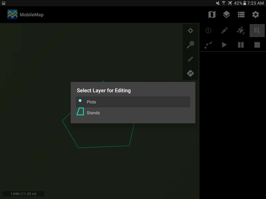
Once the polygon is created. Select ‘Select Layer for editing’ option is the tools menu on the right side to open editing option. This will list all feature types available to edit. Select the polygon layer you must edit. In this case it is ‘Stands’.
Note that you can also select an old record to edit by tapping on the polygon.
Editing Vertices
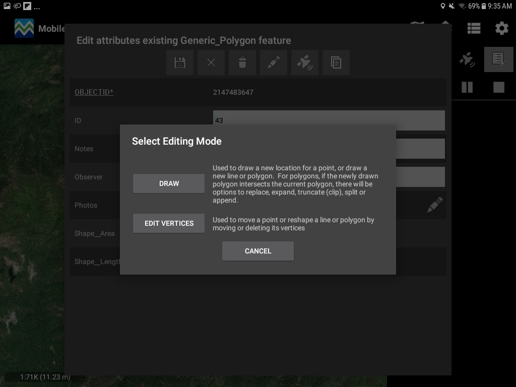
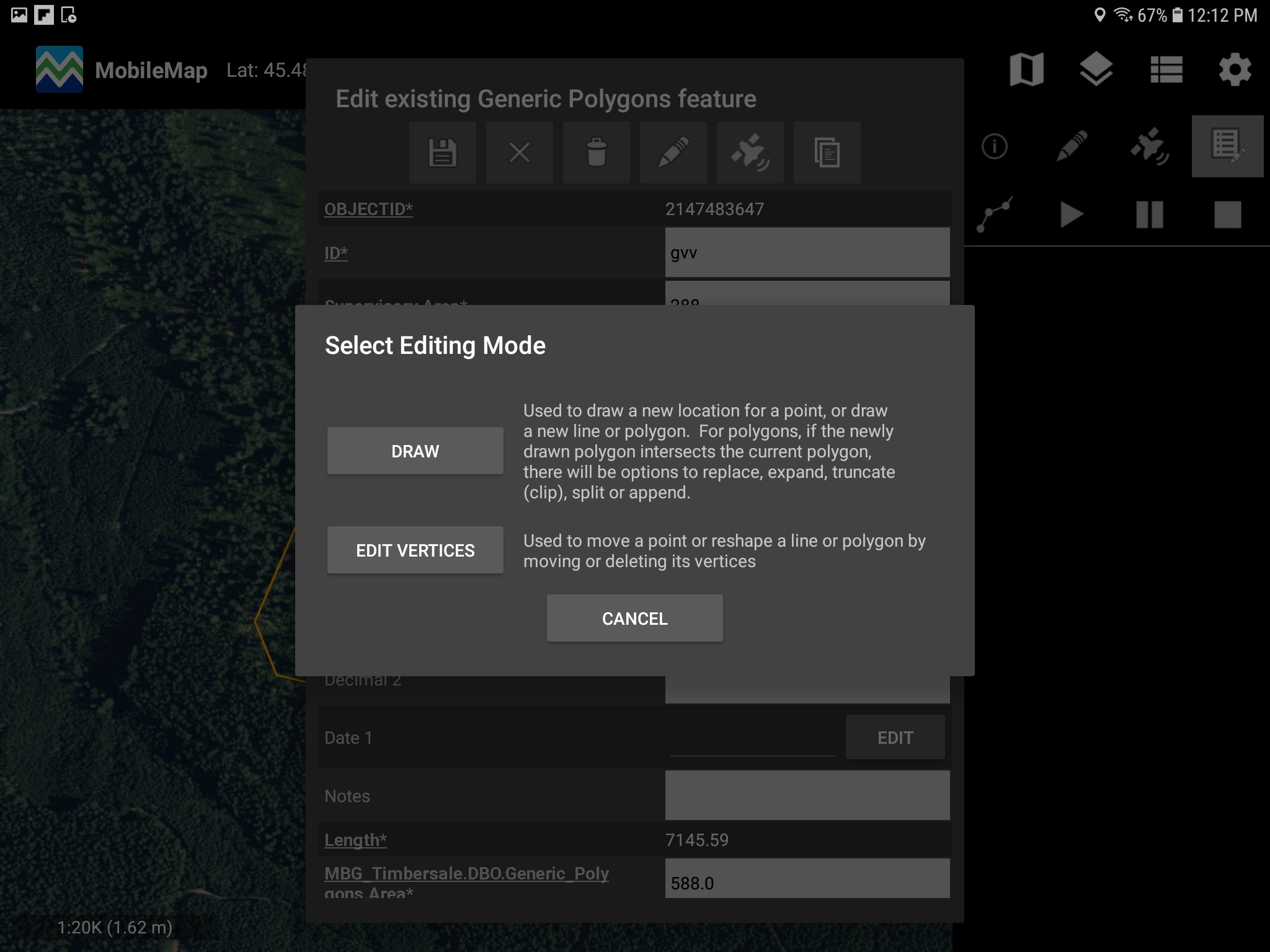
Once you have a layer to edit, the attribute of that record will pop up. Select the pencil tool again in this menu and select ‘Edit vertices’ as shown below. This will give you the option to only edit the vertices of this polygon.
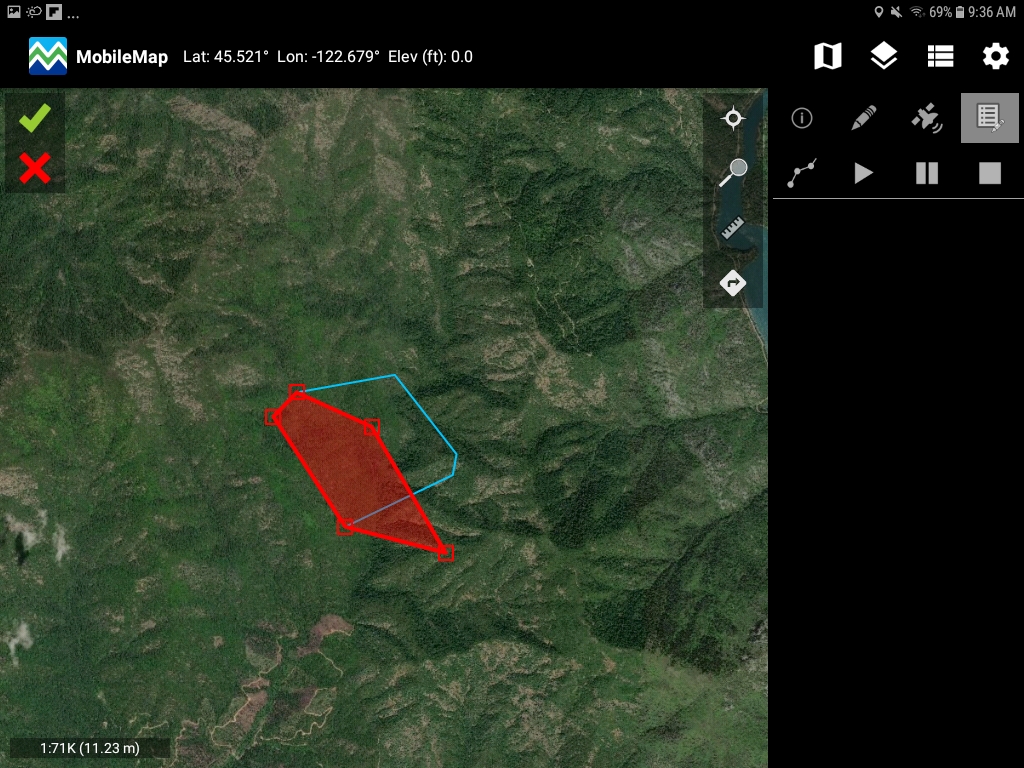
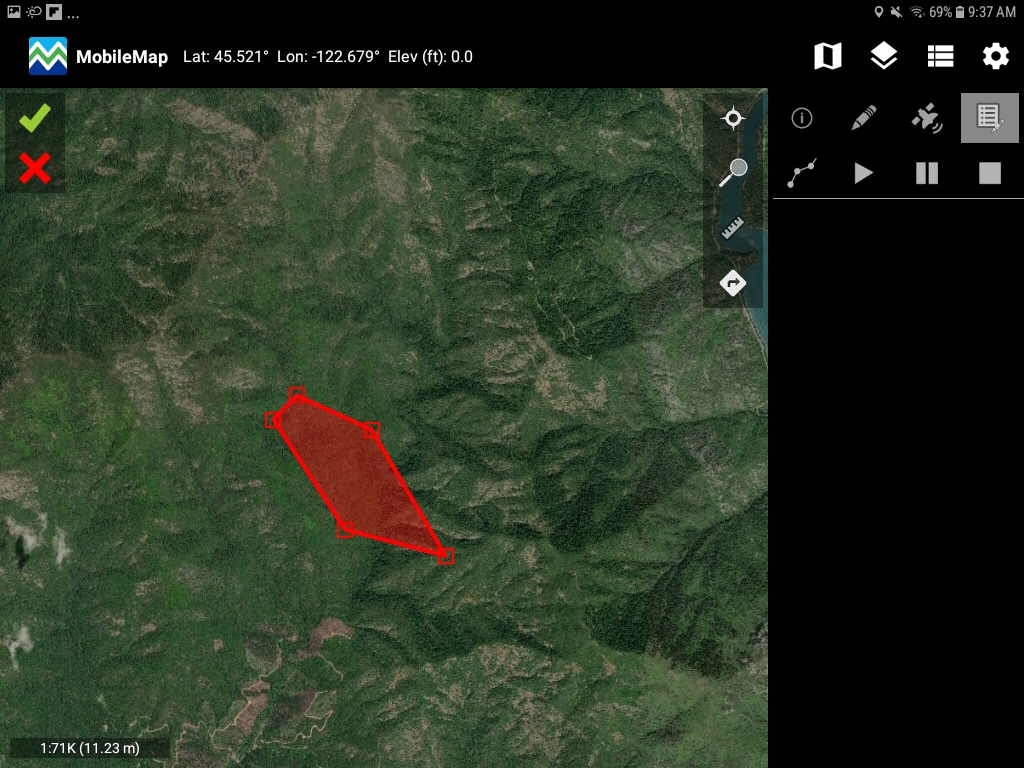
After you select ‘Edit Vertices’. The selected polygon will turn red and all vertices will show as points attached to the polygon. You will also see a green check mark and a red cross on the top left of screen. (Shown below)

Tap on the vertex you want to change, don’t’ let go of your finger from the screen, simply drag it to the location you want and let go. Below is an example of what it would look like once you expand all the vertices outwards.
Note that vertices can be dragged anywhere on the map.
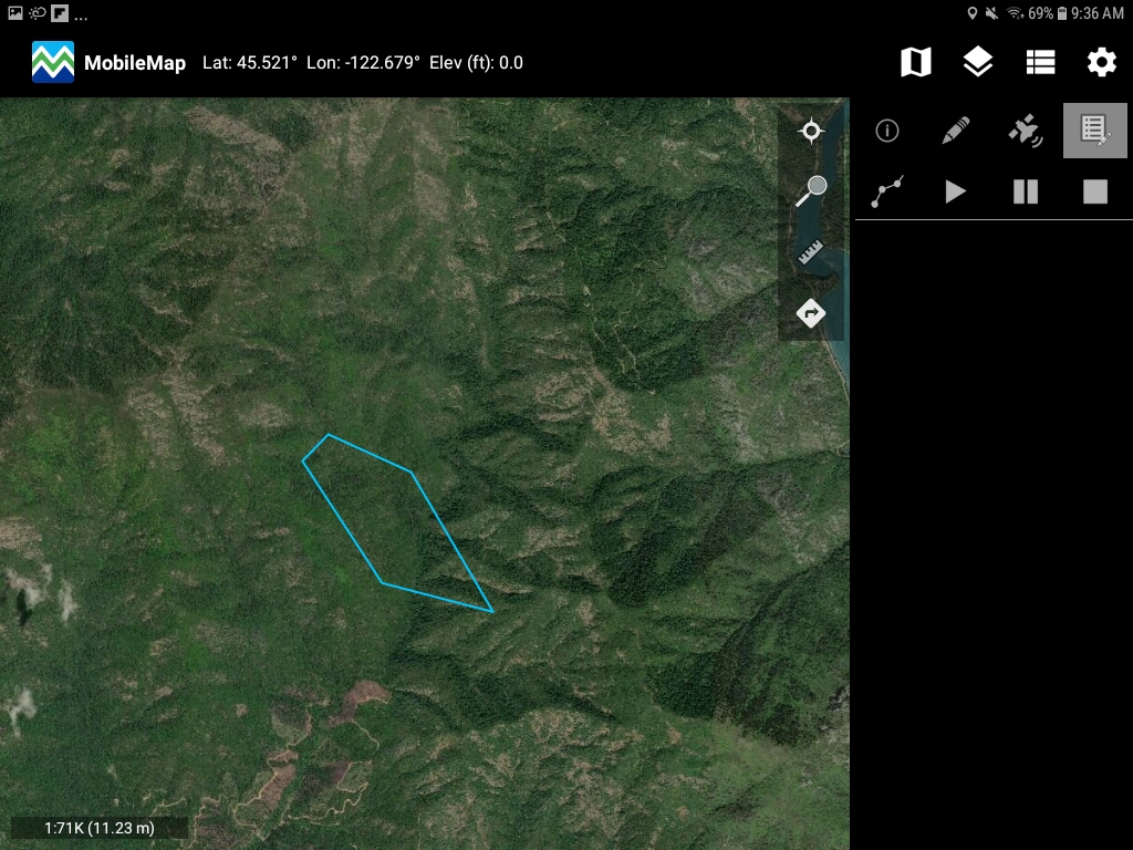
Tap on the green check mark to complete the edit. This will get rid of the red polygon and the screen now will only have a green highlighted polygon with current selected vertex locations.
Deleting Vertex
Following the same process for editing, one can delete the vertex as well to reduce the size of the polygon. Go through initial steps of highlighting your polygon. Change the vertex locations as you want. To delete a vertex, simply press on the vertex location for a fraction of a time longer than you would for editing and let go. This will delete the vertex.
As shown below, the vertex is deleted. Tap on green check mark to finish the sketch and a new polygon with less vertices is now formed. You can also tap on the red cross to redo the edit.

Draw Editing
Draw editing allows a user to draw a new location for a point, or draw a new line or polygon. For polygons, if the newly drawn polygon intersect the current polygon, there will be options to replace, expand, truncate (clip), split or append the original polygon with the new polygon. Once the user has selected the feature for editing and clicked the pencil icon on the feature attribute window (see Vertex Editing section above for these steps), they can select the Draw edit mode.
Replace the Feature
Draw a new feature in the desired location. For points and lines the new feature will replace the old feature when the new feature has been drawn on the screen. All attributes from the original feature will now be stored in the new feature.
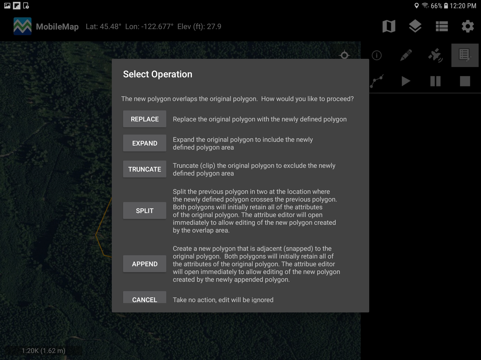
For Polygons that overlap the original polygon, the user will be given the following options:
Replace
Replace the original Polygon with the newly defined polygon
Expand
Expand the original polygon to include the newly defined polygon
Truncate
Truncate (clip) the original polygon to exclude the newly defined polygon area
Split
Split the previous polygon in two at the location where the newly defined polygon crosses the previous polygon. Both polygons will initially retain all attributes of the original polygon. The attribute editor will open immediately to allow editing of the new polygon created by the overlap area.
Append
Create a new polygon that is adjacent (snapped) to the original polygon. Both polygons will initially retain all attributes of the original polygon. The attribute editor will open immediately to allow editing of the new polygon created by the overlap area.
Project Points (available at MobileMap release 4.3.61)
It is sometimes useful to create a point at a set distance and direction from another point. One scenario is trying to find a property corner based on a distance and azimuth from a known property corner.
In MobileMap, this is accomplished by applying a spatial offset when copying a point feature. To use this functionality, first select the Identify or Edit tool, then select the feature layer for the point that marks the starting point. Note that many users disable copy of plots (Settings > MobileMap Cruise > Enable Copying of Plots) to avoid accidentally creating duplicate plots. This means that Plots typically cannot be used as starting points when projecting a new point based on a distance and azimuth. Instead, it is likely best to start with a Generic Point that is created in the office (InventoryManager or ArcGIS Pro), is digitized to imagery in the field, or is captured via GPS in the field (optionally with GPS averaging and/or a high-accuracy GNSS Bluetooth receiver). Then, copy the Generic Point to a new Generic Point while applying the spatial offset (distance and direction).
Once the source point layer has been selected, tap on the origin (starting) point to open it’s attribute table. Select the Copy tool at the top of the form. When the Copy tool opens, select the target Point layer from the dropdown list. Next, check the ‘Apply Offset’ checkbox. Finally, select the distance units and enter a distance and degrees (azimuth) for the desired new point. As with standard feature Copy functionality, use the checkboxes to opt out of copying any specific attribute to the feature that will be created.

Finally, tap the Copy button to complete the operation. MobileMap will create the new Point feature and open up the attribute form to enable update of the attributes for this new Point.
Draw Line to Next Selected Point (available at MobileMap release 4.3.61)
It is sometimes useful to create a line that connects two points. In MobileMap, this is called Drawing a Line to the Next Selected Point. To use this tool, select the Identify tool, then tap on the origin (starting) point for the line. Use the Draw Line to Next Selected Point tool (line with two end points icon), then select the line layer that the new line feature should be created in and tap ‘Proceed’.

When the dialog closes, tap on the destination point. The destination point must be the same feature type as the origin point. A new line feature will be created from the origin point to the destination point.